


1,Solution overview:
IDC is control center of high-speed internet. They are responsible for remote processing, storage and transmission of information resources. The requirement of timeliness is ultra-high. So IDC must provide users with value 365×24 continuous high-speed, safe and reliable added services of information resource.
To meet the demand of information network to realize unattended management and remote centralized monitoring and control for IDC and MDC computer rooms, internet data center should build up a set of "non-IT devices" centralized monitoring system as well as configure with the real-time monitoring network management system for its IT devices. The purpose is to monitor and analyze the real-time situation of air-conditioner, power distribution cabinet, battery units, electric generating set, leakage alarm, security system, fire-fighting system and so on. The following is the detailed illustration of each system in this solution.
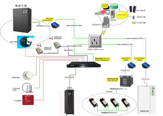
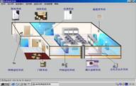
Computer Room Centralized Monitoring System Topological Diagram:
2,Security System:
IDC computer room is the core platform providing information service and management for all departments. Access to the IDC computer room needs to be controlled effectively with higher security precaution. Security system is designed based on comprehensive consideration of demand. Its subsystems include the door access system and video monitoring system.
Computer rooms have a large quantity of equipment including the network server equipment and environmental power equipment which need the operation stability of requirement. If it adopts the 24 hours special attended watching and regular time inspecting those equipment of modes which exist the human resource wasting, negligence and fatigue of workers, not enough professional skills of inspecting workers that can make the troubleshooting, unscientific and nonstandard of monitoring management problems and so on.
Security system can provide advanced management methods for the maintenance personnel. The real-time management information and plenty of historical records can improve the management level of equipment for the computer room system to achieve the scientific management as well as save the human resource to decrease the labour intensity of maintenance personnel. It can also improve the fast-speed response ability for the incidents to reduce the risks and damages caused by faults that can let the management of computer room to enter a new step.
2.1 Solution Principle
■Advanced and maturity
Considering the importance and high technological content of the computer room, the designer, in designing the system, adopts mature and advanced, scientific and reasonable, and safe and reliable technologies and products which can meet the requirement of monitoring system in the computer room.
■Openness and safety
The used product except the system which consists of present equipment can connect with the other brand product that meet the international standard, meanwhile they have good safety to prevent the attacking. The system, adopting the international TCP/IP communication protocol, HTTP protocol, SNMP protocol, TELNET protocol and so on, is applicable to operation systems such as Windows, NT/2000/XP/2003/Vista/7 and so on.
■Reliability
The applied technologies and products are highly safe and stable.
■Expandability
The used productions not only can satisfy the present needs but also can consider the further function expansion needs.
■Maintainability, manageability
The installation and configuration of system have simple, easy maintenance, using convenience and handy management characteristics etc.
2.2Door access system
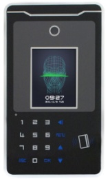
Door access system is composed of the controller, card reader, electric lock, power box, opening-door button, emergency-door button, system server (computer), communication converter, and access control and attendance management software. The method of card reading belongs to the non-contact card reading method, the card holders just need wobble the cards once in the sensing areas of card readers which can sense the cards and then to send the information in the cards (card number) to the controllers, and the controllers will check the validity of cards and then to decide whether the doors open or not. The whole processing just can achieve the door access management function in the range of valid card punching. The card reader can install inside/outside of wall of door sides which do not affect other works. It can communicate with the computer to make the real-time monitoring, data processing, inquiry, report output and so on through the RS485 (computer can remotely control the door access for all of doors or one of doors, meanwhile it can monitor the status for all of doors). The whole system adopts the entering doors need to read the cards and exiting doors need to put the button, all of doors have the emergency-opening button. The alarm signal of firefighting is also connected with the system. When there is alarm, the system will automatically be power off and open the door.
2.3 Video Monitoring System
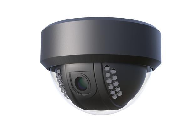
In the passages of computer room equipment areas, main gateways of computer rooms and power distribution rooms, video recorders or embedded digital hard-disk video recorders are installed to achieve the monitoring.
The video stream storage and compression technique of hard disk video recorders adopt the MPEG4 compression technique which high compression ratio, accurate and stable control of code stream, and high-definition image the quality of transmission is perfect. The hard disk video recorder has the remote browse function which the users can watch the appointed video events and replay or real-time monitor the images from the remote controlling side that does not affect the local monitoring. According to the MPEG4, it diminishes the pressure of bandwidth when the video files are browsed remotely. So when the workers of computer rooms they are out of duty the building monitoring center can control and monitor this system though the remote browse method.

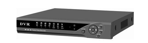
The system adopts the digital recording and the data of 24-hour video signal can be saved for 30 days. The system adopts that each video channel directly connects with the host machine which can solely record every video channel of actual conditions, it is based on the requirement of actual conditions to design it. The hard disk video recorders are located in the office areas and all of video signals are centralized in them.
3, Environment Monitoring System
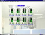
According to the demand of users, the computer room adopts one monitoring host machine. In this time of design plan it can achieve the real-time operation parameters of collecting and processing for the intelligent devices and subsystems, the main monitoring is including: power distribution monitoring, UPS monitoring, precise cooling equipment monitoring, water leakage monitoring, temperature/humidity monitoring, oil engine monitoring, fire-fighting monitoring and so on.
Main monitoring object:
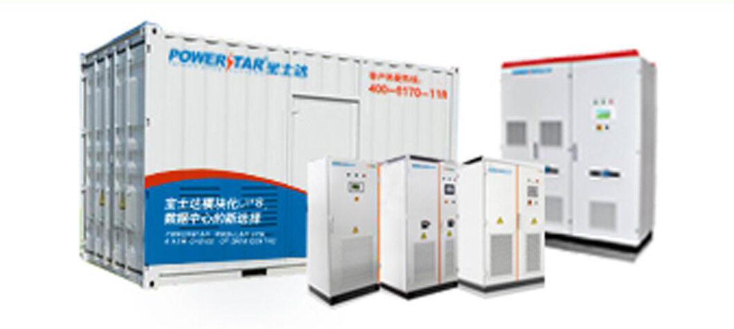
■Power distribution system;
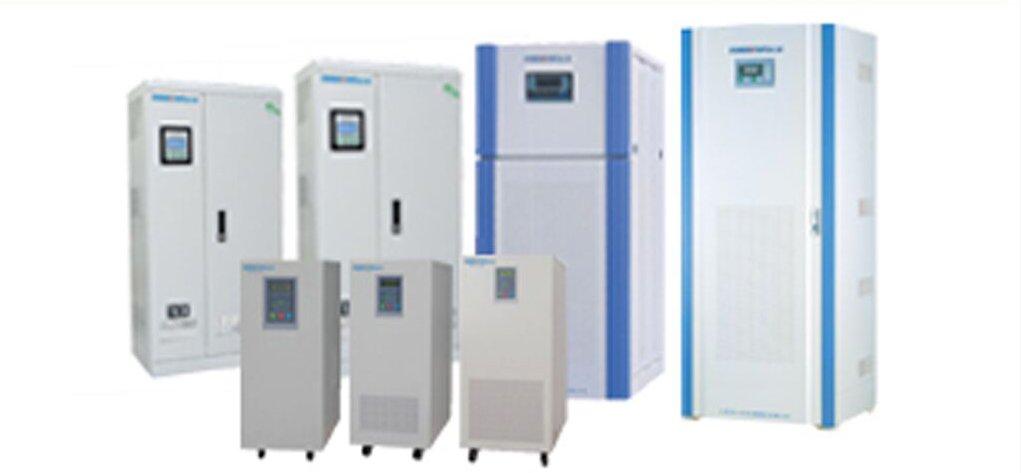
■UPS system;
■Precise cooling equipment of computer room;
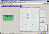
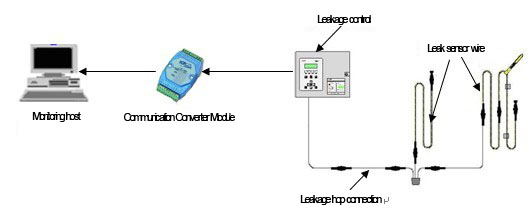
■Locked water leakage testing system of computer room;
■Temperature/humidity in the computer room;
■Oil engine monitoring;
■Fire-fighting monitoring.
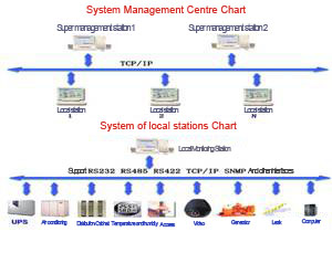
The above uniform monitoring of system can achieve the personnel unattended management to improve the reliability of system which improve the scientific management of computer room. The system can offer the many type of warnings, the software is in English, the operation is easy, and it can also support the SNMP protocol of power equipment to provide the database for the users.
System Management Schematic Diagram:
3.1 Power Distribution Monitoring
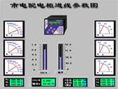
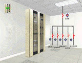
Power distribution cabinet of power distribution room, current quantity of total input wires of main power, status of all secondary contact switches of power distribution cabinet (power distribution cabinet has to add the secondary contact switch on the important switch).
■Monitoring content:
A, voltage, power, frequency, power factor and gross power of phase of input wire of main power of real time monitoring power distribution cabinet.
B, Working status of secondary contact switch of power distribution cabinet.
■Characteristics:
It can show and save the value of each monitoring parameters of total input wires of each power distribution cabinet and working status of secondary contact switch of power distribution cabinet. It can set the upper limit value and lower limit value. When the monitored voltage or current is beyond the permissible value the system can be judged as the fault (warning) the main monitoring system will immediately pop up the relative warning windows, meanwhile, the monitoring main machine will send the multimedia voice warnings and text-messages to inform the workers on duty or officer on charge. They can check any monitoring targets of historical records (lists and graphs).
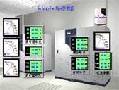
3.2 UPS Monitoring System
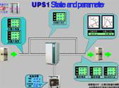
■Monitoring Targets:
UPS main machine and battery units in the power distribution room.
■Monitoring content:
A, Analogue
Input phase voltage, output phase voltage, bypass phase voltage, input phase current, output phase current, bypass phase current, battery voltage, battery current, system frequency, system load, battery standby time.
B, Digital quantity
Over-range output voltage, battery working method, bypass working method, high battery voltage, low battery voltage, system warning, system suspension, low battery voltage warning, overvoltage warning of bypass, and overvoltage of main power.
■Characteristics:
It can show and save the real-time remote operation parameters that the UPS communication protocols provide and the status of each component.
It can judge the components of UPS whether they are sending the warning. When the some components of UPS are on the failure or out of limit the main monitoring system will immediately pop up the relative warning windows, meanwhile, the monitoring main machine will send the multimedia voice warnings and text-messages to inform the workers on duty or officer on charge. They can check any monitoring targets of historical records (lists and graphs).
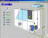
■Monitoring Targets:
It can make the real-time monitoring and management for the accurate air-conditioners in the computer rooms. It also can remotely make the centralized monitoring and management for them through the interfaces and communication protocols which the factory offered.
■Monitoring content:
A, Monitoring parts
Return air temperature, return air humidity, return air temperature upper limit value, return air humidity upper limit value, return air temperature lower limit value, return air humidity lower limit value, temperature setting value, humidity setting value, operating status of air-conditioner, operating time of compressor, percentage of heating, percentage of cooling, operating status of heater, operating status of dehumidifier, operating status of humidifier, temperature/ humidity changing graphs, compressor high pressure alarm, compressor low pressure alarm, air-conditioner water leakage alarm, temperature/humidity over-high alarm, temperature/humidity over-low alarm, humidifier fault alarm, main fan overload alarm, humidifier what-short alarm, filter blocking alarm.
B, Management parts
Remote start-up and close-down for the air-conditioner, remote setting of temperature/ humidity.
All monitoring of air-conditioner and some specific conditions of controlling are based on the communication protocol that factory offered.
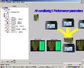
■Characteristics:
It can monitor the operation status of air-conditioner the changing of graphs and colors can show the working status of air-conditioner. When it occurs the fault it will send the warnings which include the operation status of heater, compressor high pressure fault, filter blocking and so on. The users can remotely monitor and control the air conditioners starting-up, closing-down and setting value of temperature/humidity through this monitoring system in the monitoring room.
It can show and save the real-time remote operation parameters that the air conditioner communication protocols provide and the status of each component. When the system is sending the warnings the main monitoring system will immediately pop up the relative warning windows, meanwhile, the monitoring main machine will send the multimedia voice warnings and text-messages to inform the workers on duty or officer on charge. They can check any monitoring targets of historical records (lists and graphs).
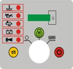
Performances and Characteristics
■Wide DC input range;
■Low oil pressure, high water temperature and cylinder temperature and over-speed protection and indication;
■Lost battery charging warning indication, non-stopping;
■One secondary outside input warning stopping signal;
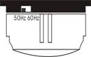
■Speed signal based on the frequency of generate electricity;
■LED displays all kinds of status of warning;
■Operation hour counting liquid crystal display;
■External frequency-selecting toggle switch;
■Fuel output, starting-up output, warming-up output, stopping output and public warning output functions, all of them are the output of relay;
■Modular structure design, ABS plastics cover, embedded installation mode, compact structure, small volume, advanced single chip control, stable performance, convenient operation.
Warning Quantity
■Low oil pressure, after the successful starting-up and delay 10 seconds it is going to make the detecting;
■High water temperature, after the successful starting-up and delay 10 seconds it is going to make the detecting;
■Over speed: when it starts it is going to make the detecting, if it remains for 3 seconds it is going to make the warning and stopping;
■The battery charging is lost, after the successful starting-up and delay 10 seconds it is going to make the detecting;
■External stopping warning input: if it is on the manual starting-up position and auto-position it is making the detecting, if it is on the stopping position it is invalid;
■Invalid starting-up: if it starts up for three times on the auto-position it doesn't work it will make the warning;
■Invalid stopping: After the 30 seconds of sending stopping signal if it doesn't stop stably the public warning light is shining;
■Non-generate electricity: After the successful starting-up and delay 10 seconds it is going to make the detecting when the voltage is under 15V for more than 5 seconds it is going to make the warning to stop the machine.
Public warning: when it occurs the over-speed, high water temperature, low oil pressure, external stopping warning input, non-generate electricity, invalid starting-up and invalid stopping warning the public warning light is shining and outputting.
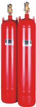
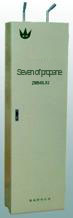
1,It adopts the heptafluoro-propane extinguishing device without piping system.
2,Design of protection area: this extinguishing fire area of project are three-layer computer room and two-layer equipment room if it designs for one protection area the protection structure of protection area and fire resistance time of door/window cannot be less than 0.5h the taken pressure strength of protection structure cannot be less than 1.2Kpa. When the fire is extinguished in the protection area it need to keep the sealing condition.
3,Gas selection description: the halo alkane (1211,1301 etc.) gas is forbidden to use for the fire extinguishing in the world in the recent years. Some of small toxicity, non-pollution and high efficiency of "green" gas replace them. Now the halo alkane gas has withdrawn from the market. The heptafluoro-propane gas is widely used that we choose it for this project. The chemical formula of extinguish ant heptafluoro-propane (HFC-227ca) is CF3CHFCF3 which meets the international standards of "green" fire extinguishing gas. From the view of fire extinguishing gas, the heptafluoro-propane extinguishant is the first choice in the future. The heptafluoro-propane extinguishant is used in the following fire conditions: electrical fire, combustible liquid fire, Melted solid fire and surface of solid fire. Before extinguishing fire it should cut off the gas fire of gas supply etc.
4,Fire-fighting warning description:
Computer room adopts the smoking and temperature sensors. They are distributed in the floor, working-layer, working layer of two-layer equipment room in the computer room. When the fire occurs the smoking and temperature sensors are warning together the air conditioner and electric of non-fire fighting are firstly cut off, and then it is conformed after 30 seconds the gas extinguishing system is opened up under the automatic, manual, linkage situation.
In this system, AC power supply should adopt special fire-fighting electricity. Other non-fire-fighting devices must not be connected in the circuit. The power supplying system operates normally and charges the backup power supply which will work during power failure.
4, Conclusion:
Above is the solution to computer room monitoring. Monitor content and monitor target can be developed and applied in line with users’ specific requirement. Also users can select part of them to carry out monitoring solution.